Hot search keywords : Control cableSoft sheathed cableComputer cableRS485 cable
Modern buildings in the office building, and large shopping malls of the super large public buildings, the system is very complex, which the mineral cable construction process to give you a brief introduction, but the technical requirements to the national standards as a reference basis, which because the cable insulation material (magnesium oxide) in the air is easy to absorb moisture, the construction must do moisture-proof measures, otherwise it will cause cable damage. The resulting loss is borne by the construction party, please be sure to comply with, in strict accordance with the specification of construction, remember to remember. About mineral insulated cable laying Qingdao Tianxing cable Mineral cable construction suggestions, mineral cable damp recommended treatment methods.
1 Construction Preparation
1.1 Before laying the cable, check whether the cable is in good condition and measure whether the insulation resistance meets the requirements specified in the standard.
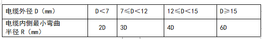
All the paths of cable laying should meet the requirements of the allowable bending radius of the cable specified in the following table:
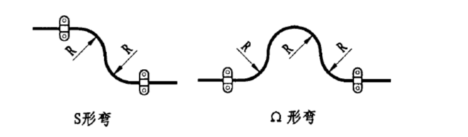
When the cable is laid in the following occasions, due to environmental conditions may cause cable vibration and expansion, it should be considered to lay the cable into an "S" or "Ω" bend, and the bending radius should not be less than 6 times the outer diameter of the cable.
1.1.1 In places with large temperature changes.
1.1.2 Wiring of vibration equipment, such as motor inlet line or generator outlet line.
1.1.3 Between the settlement joint and expansion joint of the building.
1.1.4 All cables are laid in straight lines.
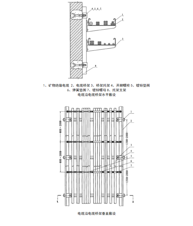
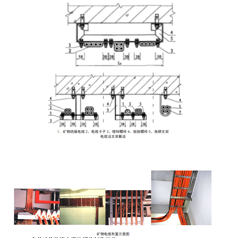
2 Cable laying
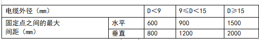
2.1 When laying cables, the spacing between fixed points shall meet the requirements in the following table:
2.2 In the open application part, if the cable of the same direction has large, medium and small specifications, from the perspective of tidiness and beauty, it can be fixed according to the cable standard requirements of specifications, and it can also be fixed by the interval. When the cable is laid at a tilt, when the cable is 30° or less from the vertical direction, it is fixed according to the vertical spacing; When the value is greater than 30°, it is fixed according to the horizontal spacing.
2.3 Various laying methods can also be fixed by one fixed point per meter.
2.4 When laying the cable, at the turning point and on both sides of the intermediate connector, if conditions are fixed, they should be fixed.
2.5 When calculating the length required for laying cables, consideration shall be given to leaving a margin of not less than 1%.
2.6 When laying a single-core cable, a gap of not less than 2 times of the outer diameter of the cable should be left between each cable. If no gap is left, the reduction factor of carrying current should be considered.
2.7 Appropriate protective measures shall be taken for parts of the cable that may suffer mechanical damage during operation.
2.8 When laying single-core cables, lay them one by one. After each group is lined and straightened, arrange and bundle them. The bundling interval is 1 to 1.5m.
2.9 When cables are laid in an environment that corrodes copper sheaths, or when partially buried or laid through pipes, cables with PVC sheaths should be used.
2.10 Single-core cables are not allowed to be laid through metal pipes alone.
2.11 In the process of wiring, the end of the cable should be temporarily sealed immediately after the sawing.
2.12 Cable terminals, intermediate couplings, laying accessories and special tools for construction shall be supplied by cable manufacturers.
2.13 The installation of cable terminals and intermediate couplings shall be carried out in strict accordance with the installation process, specifications and specifications recommended by the cable manufacturer.
2.14 As the insulation material (magnesium oxide) of the cable is easy to absorb moisture in the air, moisture-proof measures should be taken during construction. When moisture is found to invade the cable end, the damp section can be cut off; You can also use the torch flame directly to heat the damp section of the cable, and the flame must be moved to the cable terminal until the insulation resistance of the cable is detected with a 1000V megohm meter to reach more than 200MΩ, before the terminal and the intermediate connector can be installed.
2.15 During the installation of the terminal and intermediate connector, measure the insulation resistance of the cable several times in a timely manner. If the cable is damp during installation or the metal debris is not cleaned up, the insulation may be unqualified.
The wire connection of the cable terminal and the intermediate connector can choose a variety of connection methods such as confining pressure, point pressure, nut pressure, screw crimping, and plate crimping.
2.16 The terminal of the cable should be firmly and reliably fixed on the electrical equipment. When the copper sheath of the cable is used as the ground cable, the ground should be reliable.
2.17 When cables are laid in parallel, if there are multiple intermediate couplings, their positions should be staggered.
2.18 The terminal core wire phase sequence should be connected correctly and the color code should be obvious.
2.19 After the installation and construction of the terminal and intermediate connector of each cable, the insulation resistance test shall reach more than 100MΩ before delivery.
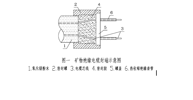
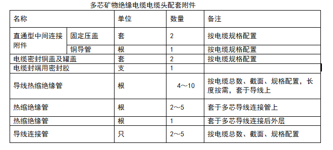
3 Multi-core mineral insulated cable terminal production process
3.1 The installation of multi-core mineral insulated cables is the installation of sealed copper can terminals. Due to the number of cores of the multi-core cable and the relatively small cross section, when installing the terminal, special attention should be paid to the wire and wire, the wire and copper sheath, the distance between the wire and the sealed tank, and the insulation resistance to ensure the installation quality of the terminal. For supporting accessories, see below:
3.2 Installation Process:
3.2.1 Positioning: To determine the cable fixing position, drill a fixing hole in the ground support, distribution box, or cabinet shell according to the diameter of the screw on the cable fixing cover body, bend the cable to the device wiring point, measure the length to be peeled off the copper sheath of the cable. The stripping length is the length from the fixing hole to the device wiring point, and saw off the excess cable.
3.2.2 Fixing Cables: Remove the front nut of the cable fixing gland, insert the rear nut, compression ring, and gland body into the cable in turn, and then insert the cable into the installation hole of the ground support or distribution box or cabinet to drill holes. Because the stripping length of the cable copper sheath is long, pull the stripping incision of the cable out of the gland by about 150mm, and then place the gland body in the installation hole. Screw the upper nut to temporarily secure the cable to the support or cabinet.
Insulation test: The insulation resistance of each core of the cable is tested with a 100 meohhm meter. The insulation resistance between the measurement wire and the conductor, the insulation resistance between the conductor and the copper sheath, should be above 200MΩ. If it is below 200MΩ, the damp place should be found out and the tide should be driven by the torch flame until it reaches more than 200MΩ.
3.2.3 Peeling off the copper sheath: mark the copper sheath stripping incision, peel the cable copper sheath with the cutting tool roll, peel to the mark, clamp the cable under the tool with wire pliers, continue to rotate the tool, peel off the copper sheath, in the process of rolling and stripping, the copper sheath is too long, should be cut off and continue to roll and strip. After stripping the copper sheath, separate the cable core and wipe the magnesium oxide powder off the wire with a dry cloth or clean cotton yarn.
3.2.4 Insulation test: The method is the same as before, mainly to check whether the wire and the copper jacket at the stripping place touch the wire, if so, clean up immediately to ensure the installation quality.
3.2.5 Installation of sealed copper cans: Clean the burrs at the edge of the copper protective layer, then wipe the copper wire and copper protective layer with a dry cloth or clean cotton yarn, and insert the brass sealed copper can. The copper can and the cable should be kept perpendicular to each other so that the internal thread at the bottom of the copper can is gradually tightened on the copper sheath. After twisting 1 or 2 buttons, use torque pliers to clamp the ktumble section at the bottom of the copper can and continue to tighten it downward until the thread of the copper can is even with the copper protective layer of the cable.
3.2.6 Fill the sealing insulation filler: At this time, test the insulation resistance of the cable again to prevent copper chips from touching the wire during the tightening of the copper can. Then pour the sealing insulation filling glue into the copper irrigation, if the putty type of filling glue, then use your finger from the side of the jar to the jar mouth flat, then put into the jar lid, the glue slightly overflow, and clean up.
3.2.7 Heat shrink insulation bushings: Insert the heat shrink insulation bushings into each exposed copper wire respectively, and cover the pot cover directly, and then evenly heat the pot cover upward with a blowtorch, so that the heat shrink tube evenly shrinks on the wire.
3.2.8 Fixing the Cable: Loosen the front nut of the temporary fixing gland of the cable, pull the cable out backward, and pull the end of the cable sealing copper can into the gland body. Then tighten the rear gland nut to secure the cable, tighten the front gland nut, and secure the cable and the gland to the support or the shell of the distribution box or cabinet.
3.2.9 Check the phase of the conductor: Check the phase of the conductor at both ends of the cable with a nuclear phase meter or a multimeter, and mark the phase sequence.
3.2.10 Terminal Connection: Bend the cable to the wiring point according to the phase sequence of the cable, measure the connection position between the copper wiring terminal and the wire, cut off the excess copper wire, and insert the copper wiring terminal. If the terminal is pressed, tighten the clamping nut of the terminal with a wrench; If crimping terminals, use crimping pliers to crimp copper terminals. If the cross-sectional area of the cable wire is small and the terminal connection is not used, then the top of the wire can be bent into a leg ring, which can be connected with the device with screws, and the leg ring size depends on the size of the connection bolt.
3.2.11 Insulation test: Test the insulation resistance of the cable again according to the steps in previous 2.3. Generally speaking, the test should be good at this time, and it should be above 200MΩ. If the insulation resistance is low, it indicates that there is a problem with the operation, which should be found out and rectified.
3.2.12 Connecting the Cable to the Device: Bend the cable one by one according to the phase sequence of the cable and the phase of the connection to the device, and connect the cable to the device with bolts. Just tighten it with a wrench.

4 Multi-core mineral insulated cable intermediate connector
4.1 The intermediate head of the multi-core mineral insulated cable is installed using a sealed copper can type intermediate connection attachment. Because the wire of the multi-core cable has 2 to 5 core wires, and the cross section of the wire is relatively small, the cross section is 25mm2, so in the production and installation of the intermediate joint, not only to ensure the distance between the wire and the wire, the wire and the copper sheath, but also to ensure the insulation resistance value of each core wire. In order to reduce the volume of the connecting section of the conductor and reduce the diameter of the copper casing of the connecting attachment, the dislocation connection method is adopted, which increases the complexity of the middle connection of the multi-core mineral insulated cable. To this end, in the actual construction, it is necessary to calculate the size and specific position of each core wire connection according to the intermediate connection accessories provided by the manufacturer, ensure the spacing, and deal with the core wire insulation, only in this way can ensure the construction quality of the joint. For supporting accessories, see the table below
4.2 Installation Process
4.2.1 Positioning: Take the middle of the cable crossing at both ends of the cable as the middle of the connector, and bend the cables at both ends. When possible, make an "S" bend or "Ω" bend at the back of one end of the cable for backup. Straighten both ends of the cable and cut off the excess cable by adding 300mm to each end of the hacksaw in the middle of the connector.
4.2.2 Insulation test: The insulation resistance of each core of the cable is tested with a 1000V meohhm meter. The insulation resistance between the conductor and the conductor, and between the conductor and the copper sheath, should be above 200MΩ. If it is lower than 200MΩ, the damp place should be found and the tide should be driven by the torch flame until it reaches more than 200MΩ.
4.2.3 Insert middle connector accessories: Insert a set of cable fixing gland and a heat shrinkable insulation tube on one end of the cable, and insert a set of cable fixing gland and copper sheath on the other end of the cable, and place them on the cable behind the middle connector.
4.2.4 Stripping the copper sheath: According to the length of the copper sheath, determine the stripping length of the cable at both ends, make a mark on the copper sheath stripping incision, peel the cable copper sheath with the stripping force, peel to the mark, hold the cable under the tool with wire pliers, continue to rotate the tool, peel the copper sheath, in the rolling process, the rolled out copper skin is too long, should be cut off and continue to roll stripping. After stripping the copper sheath, separate the cable core, wipe the magnesium oxide powder on the wire with a dry cloth or clean cotton yarn, remember not to blow with mouth.
Insulation test: same method as above.
4.2.5 Installing a sealed copper can: Clean the burrs at the edge of the copper protective layer, and wipe the copper protective layer of the cable and multiple wires with a clean cotton yarn or dry cloth. First, put a brass sealed tank on one end of the cable, which is used to rotate the copper tank. The copper tank is required to keep vertical with the cable, and cannot tilt, otherwise it will touch the line. Make the inner thread of the lower part of the copper tank gradually twist on the copper protective layer mouth, after twisting 2 to 3 teeth, then use carp pliers to clamp the kryptoid section of the lower part of the copper tank, and continue to tighten it downward until the inner thread mouth of the copper tank is flat with the copper protective layer mouth of the cable. The sealed copper tank of the other end of the cable is also tightened in the same way as above.
4.2.6 Filling sealed insulation glue: Test the insulation resistance of the cable core wire with a megohm meter to prevent wire collision during the tightening of the copper can. Then fill the copper can with sealing filling insulation glue, if it is a putty sealant, then use the big female finger lined with a layer of plastic paper gradually from one side of the copper can into the tank; If it is gelatinized, it is also gradually injected from one side of the copper can until it is full to a little benefit from the other side of the copper can. It should be noted here that if the middle head of the vertical connection is a sealant filled with glue, the top-down end of the cable should be bent upward, and the copper can be flattened upward, and then the sealant filled with insulation can be injected. After the pot is full, put the porous insulation sealant cover into the pot, so that the glue is slightly spilled, and clean up, or use the lid crimper, or use a screwdriver to align the mouth edge of the copper pot with the three-point gap of the pot lid to tighten the pot lid.
4.2.7 Heat shrink wire insulation tube: First determine the staggered spacing of the middle connection of each core wire, and then insert the heat shrink insulation tube according to the retention length of each core wire, and slowly heat the heat from the tank cover to the wire connection with a blowtorch to make the heat shrink tube shrink evenly.
4.2.8 Wire connection: If the sealing filler is putty, the wire connection can be carried out after the heat shrink insulation tube is shrunk; If the filling glue is liquid, the wire connection can only be carried out after 24 hours, after the sealing filling glue is cured, because the glue is not cured, the wire core is touched when the wire is connected, which will lead to poor sealing of the glue in the copper tank, and the installation quality cannot be guaranteed. The method of wire connection is as follows: each core is first inserted into the thermal insulation tube used for wire connection, and the length of the sleeve is long with the wire core; If it is a two-core wire, it is necessary to consider the staggered connection points of the two wires; If it is a three-core wire, consider the indirect one, the other two cores staggered before and after the connection; If it is a four-core cable, it can be trapezoidal staggered core wire connection; If it is a five-core cable, one bus should be considered in the middle, and the other four staggered cores should be connected. In the actual installation and construction, the length and caliber of the copper conduit should be specifically taken into account, and the connection of the multi-core wires should be reasonably arranged, taking into account that after the wire connection, the copper conduit should be covered without touching the line, and the copper conduit can rotate freely. After the core wire is properly connected, the wire end conductor is inserted into the copper connecting pipe, and the hydraulic clamp is used to crimp the wire according to the requirements. After the core wire is fully connected, the overheated insulated pipe is moved to the joint of the nozzle, and the heat is heated separately to make it shrink evenly.
4.2.9 Insulation sleeve of heat shrink joint: Gather up multiple wire cores, move the heat shrink insulation tube of the joint to the middle of the joint, use a blowtorch to gently heat and shrink evenly from the middle to both ends, and then test the insulation resistance of the cable.
4.2.10 Installing intermediate connection accessories: Move the copper conduit to the middle of the connector, move the fixed gland from one end of the cable, and connect with the thread of the copper sleeve for tightening; The fixed gland on the other end of the cable is moved to the other end of the copper sleeve, and the threads at both ends are connected to each other. After tightening, use a wrench or pipe pliers to tighten the nuts after fixing the gland at both ends.
4.2.11 If the middle connection head is in a high temperature place, then the sealed copper tube can not be filled with glue, but replaced with glass powder, heat shrinkage is replaced with a small porcelain tube, before the wire connection into the core, after the wire connection, and then one by one in the connection outside the tube, and then in the middle of the joint wrapped two layers of non-alkali glass ribbon, to prevent the small porcelain tube vibration. If the porcelain tube is used as insulation, the diameter of the copper conduit in the middle connection attachment should also be enlarged accordingly, so that the middle connection head of the cable can be placed in the copper sleeve.
Qingdao Tianxing cable Co., Ltd. focus on matching
Telephone : +86 16678668098 Mailbox : Aibrave@tianxingcable.cn Address : Dazhuge Industrial Park, Jiaozhou, Qingdao, Shandong Province
 Public account
 Official Douyin
 Enterprise Tiktok